Abby’s Guide > Outdoor Power Equipment (Lawn Mowers, Snow Blowers, Chain Saws and more) > Discussions > Ariens Project #4
Outdoor Power Equipment (Lawn Mowers, Snow Blowers, Chain Saws and more) Discussions |
|
jrtrebor
 
Location: Michigan - 3 hours north of Chicago on the lake
Joined: Feb 9, 2010
Points: 539
![]()
|
 |
Ariens Project #4
Original Message Oct 15, 2011 5:35 pm |
|
Finished redoing the dash on my blower The new Honda 13hp engine I got to repower the blower (again) was in great shape. Has the electric start and a 10A charging coil. But it didn't have any of the wiring. No key switch, no rectifier, nothing. All the factory stuff is way out of my budget so It had to go old school. With an ignition on/off switch. (The old one that was still on the blower) And a starter push button. Which meant that I had to rewire the whole ignition system from the engine to the dash. That is how things got started. Then being the way I am, I couldn't just run new wire and leave it at that. What's the fun it that. Anyway it's finished. Just need to get a new impeller bearing and flanges and I can put the whole blower back together and mate it to the tractor.  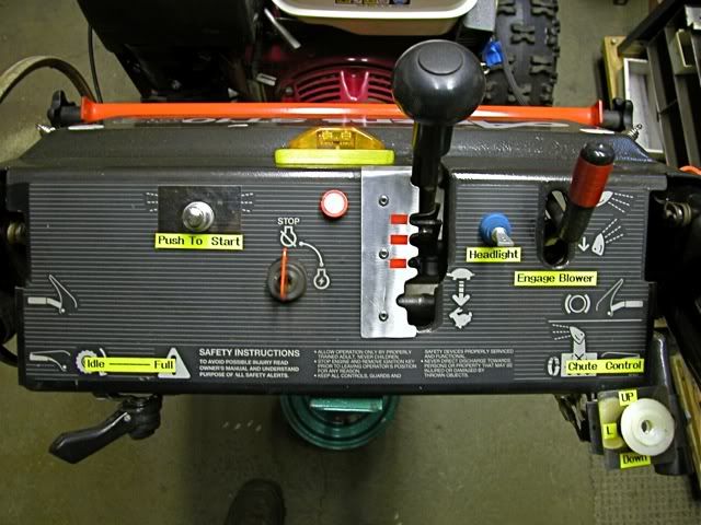
This message was modified Oct 18, 2011 by a moderator
|
jrtrebor
Location: Michigan - 3 hours north of Chicago on the lake
Joined: Feb 9, 2010
Points: 539
![]()
|
 |
Re: Ariens Project #4
Reply #39 Nov 6, 2011 11:30 am |
|
Reading the voltage directly from the coils and not through the rectifier, Set the meter to AC and take a reading. If the reading is strange switch the meter to DC and take the reading. If you are getting a reading in the 12.5 to 15 Volt range your charging coils are putting out DC and not AC and you don't need the rectifier. You may see higher voltages than that with no battery hooked up, Even at 15vdc and only 10 total amps available you will not hurt the battery if the voltage is a little high.
If you are getting DC voltage in that range you can hook up your coil directly up to the solenoid post and ground. Make sure to connect the positive side of the output to the correct post on the solenoid, the ground can go to any ground point on the engine/frame.
Remember take these readings without the rectifier hooked up.
Good luck. Well here is what I got. As I posted before there are actually four wires (two pairs) that come out from behind the shroud. Each pair are joined together to give you one wire with a connector on the end. See photo in Reply #18. (I never have really understood the two wires to one wire, unless there are four coils. Maybe I should call Honda and see if they could give me an explanation). Black probe to grnd. Red probe inserted into the wire connector Engine @ idle reading from left wire - meter set to VAC 3.6V to 3.9V Engine @ idle reading from right wire - meter set to VAC 1.6V to 1.7V Engine @ full throttle reading from left wire - 12.5V steady Engine @ full throttle reading from right wire - 5.3V steady With meter set to VDC Left wire 0.01V Right wire 0.01V If I had to take an uneducated guess I would say that I may have a coil that's not right. 5.3V compared to 12.5V. But what do I know. Maybe in all my switching wires around in the beginning trying to figure out the rectifier hook ups I burned up one of the coils. I know there is a chance that I at one time I had the ground terminal on the rectifier swapped with one of the + output terminals on the rectifier. I had the first terminal and third terminal hooked up backwards. I think. If I did would, or could that have burned out or damaged one or more of the coils? If so, I guess that could explain the wide difference in readings between the two coil wires
This message was modified Nov 6, 2011 by jrtrebor
|
jrtrebor
Location: Michigan - 3 hours north of Chicago on the lake
Joined: Feb 9, 2010
Points: 539
![]()
|
|
|
Re: Ariens Project #4
Reply #41 Nov 6, 2011 4:49 pm |
|
Well from your readings it is putting out AC and not DC. What reading do you get when you set the meter to AC and probe both wires at the same time. If it is actually AC output you dont want to ground either of those wires. You would only ground the negative wire after it was rectified to DC.
At this point I would take the shroud off and see exactly where the wires are coming from and how many coils you have. Okay I pulled the flywheel. I have two coils, each coil has two wires coming. All four wires are the same color. One wire from coil "A" is joined to one wire from coil "B" The second wire from coil "A" is joined to the second wire from coil "B" The two wires that have connectors on the end that I have been connecting to the rectifier. Have a wire from coil "A" and coil "B" It is supposed to be a 10A coil system. Flywheel has 4 magnets. This mean anything to anyone? While I have things apart. Is there a way for me to check the coils with an ohmmeter to see if they are okay? If so any thoughts as what kind of readings I should get if they are okay. And what I should see on the meter if they are bad, or partially bad or shorted. This morning I hooked an ohmmeter between the two coil wires. That is the two wires that have connectors on the end. Not the two that come off of each coil. "I got a tone". I probably should have gone between a wire and ground as well. Maybe that reading would mean something to those that know about these things
This message was modified Nov 7, 2011 by jrtrebor
|
manjestic
Location: North Shore, MA
Joined: Oct 30, 2011
Points: 87
![]()
|
|
|
Re: Ariens Project #4
Reply #42 Nov 7, 2011 10:00 am |
|
From your description of the splicing, the coils are in parallel. A single phase rectifier fed by two coils to my mind implies the coils are in phase. I'm not sure if each coil should have the same voltage output. In parallel the voltage across them must be equal but independently, this is not true. I'm thinking there is nothing wrong with your coils; there are two to produce more current than a single coil. I'm a little rusty on this stuff.
Are you removing the splice? How are you checking the coil voltages independently?
Since AC, wire color does not matter, your rect/reg will flip the negative half of the alternating current into positive. Your voltage at the solenoid and battery will vary with RPM and battery voltage. That is, even with a regulator, the output of the regulator will be higher when the battery is not at full capacity, than when it is at full capacity. If your battery is significantly drained, I wouldn't necessarily be concerned about the high voltage on the output of your regulator (battery post). I assume you are keeping a load on the output, as JimmyM says.
Paul
|
jrtrebor
Location: Michigan - 3 hours north of Chicago on the lake
Joined: Feb 9, 2010
Points: 539
![]()
|
|
|
Re: Ariens Project #4
Reply #43 Nov 7, 2011 11:06 am |
|
Are you removing the splice? How are you checking the coil voltages independently?
Paul Hi Paul I don't know or understand much about these type of things. I had been checking the output by taking a reading from each wire with the meter set to VAC. Red probe to to wire black probe to ground. But I was assuming that each one of the two wires were connected to a single coil (that is the two wires that were being connected to the rectifier. Which now seems not to be the case. As you said, the coils appear to be hooked in parallel. So I'll have to think about what that means as far as readings go. Thanks for your input. I know very little so any information is a help. I tend to be able to understand what things do, but have no clue how some things work.
|
manjestic
Location: North Shore, MA
Joined: Oct 30, 2011
Points: 87
![]()
|
|
|
Re: Ariens Project #4
Reply #45 Nov 7, 2011 11:56 am |
|
I had been checking the output by taking a reading from each wire with the meter set to VAC. Red probe to to wire
black probe to ground. But I was assuming that each one of the two wires were connected to a single coil (that is the two wires that were being connected to the rectifier. Which now seems not to be the case. As you said, the coils appear to be hooked in parallel. So I'll have to think about what that means as far as readings go.
Am I correct in thinking that you were were alternately measuring each of the two wires across chassis ground. I'd be interested in what the AC voltage across both wires (no chassis ground) is at idle and full throttle, and with and without the rectifier/regulator (and load) connected. I hope I'm not covering ground already er...covered. What I'm after is how the two wires (representing the two coils in parallel) are connected to the rectifier.
|
jrtrebor
Location: Michigan - 3 hours north of Chicago on the lake
Joined: Feb 9, 2010
Points: 539
![]()
|
|
|
Re: Ariens Project #4
Reply #46 Nov 7, 2011 3:29 pm |
|
Am I correct in thinking that you were were alternately measuring each of the two wires across chassis ground. I'd be interested in what the AC voltage across both wires (no chassis ground) is at idle and full throttle, and with and without the rectifier/regulator (and load) connected. I hope I'm not covering ground already er...covered.
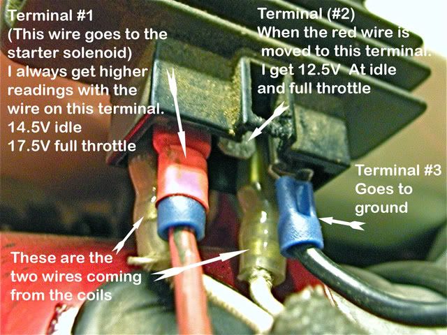
What I'm after is how the two wires (representing the two coils in parallel) are connected to the rectifier. Thanks carlb - This is sometimes part of my problem I don't even know how to correctly hook up and check things. And yes I was "measuring each of the two wires across ground". I'll have to put things back together and take a measurement across both of the wires coming from the coils. The readings given in the photo below were taken with the battery hooked in the system. I hadn't checked it that day but when I checked it yesterday it was reading 12.4V. I'll put it back in the charger and make sure it has a full charge. The diagrams that I have found for this rectifier. And the wiring diagram for the tractor that it came off of. Show or call terminal #1 the Batt + terminal. The wire runs from the rectifier to the key switch B+ terminal. Along it's way there it is tapped into and that wire goes thru a main fuse and connects to the Battery + terminal. Terminal # 2 is called or referred to as the Ign. terminal. The wire goes from the rectifier to the key switch Ign. terminal. Along its way there it is tapped into and that wire goes to a small 3 fuse, fuse block. I hope some of this is making sense I really appreciate all you guys help with this. I can do a lot of things. But I can get lost when it comes to this kind of stuff. As you can imagine with me taking readings from the coils wires with one probe to ground. I've simply been trying my best not to burn something up. By doing something stupid. That I didn't know was stupid to do. You won't be insulting me by stating simple, (doesn't everyone know this) kind of things.
This message was modified Nov 7, 2011 by jrtrebor
|
carlb
Joined: Nov 15, 2010
Points: 279
![]()
|
|
|
Re: Ariens Project #4
Reply #47 Nov 8, 2011 4:08 am |
|
I must say i have not seen a rectifier with two hot output terminals on it, but it may be more common on tractors than snow blowers. The light might be fine with the 17.5 volts while that would be too high for maintaining the battery. Maybe use term 1 @ 17 volts for the light and term 2 @ 12.5 for batt charging. Term one may be limited by a voltage regulator built into the rectifier
This message was modified Nov 8, 2011 by carlb
|
jrtrebor
Location: Michigan - 3 hours north of Chicago on the lake
Joined: Feb 9, 2010
Points: 539
![]()
|
|
|
Re: Ariens Project #4
Reply #48 Nov 8, 2011 5:09 am |
|
I must say i have not seen a rectifier with two hot output terminals on it, but it may be more common on tractors than snow blowers. The light might be fine with the 17.5 volts while that would be too high for maintaining the battery.
Maybe use term 1 @ 17 volts for the light and term 2 @ 12.5 for batt charging.
Term one may be limited by a voltage regulator built into the rectifier I think there a few out there, but not many snow blowers have an on board 12v electrical system. It's almost impossible to find information and any type of wiring diagrams for the setup I've got. Actually I haven't found any. That is why I've been using the Honda HT3810 tractors system as a guide for what I'm doing. I figure that it doesn't matter whether the system is on a tractor or a snowblower. But maybe I'm wrong about that. All I'm hoping to accomplish is to be able to run my light without draining the battery to the point the I can't use the electric starter to start it the next time out. Last year with the 11hp Honda clone and the 3A coil. I never had a low battery problem unless I had been using the light for a while. Usually if I did, I would throw a trickle charger on it overnight and things would be fine. The light is only got a 25 or 35W bulb so I'm not needing that much output from the coil(s) to keep the light running and at the same time be giving the battery a little charge. I'm going to put the flywheel back on this morning and take another reading from the coil wires. Meter in VAC mode. With one probe to one wire and the other probe to the other wire. Then I'll make sure that the battery has a full charge. Hook it up in the system and take readings again off the starter solenoid terminal. With the red wire on terminal #1 and then with it on terminal #2. Would there be any reason, or would it make any sense to you. That for some reason terminal #1 needs to be hooked directly to the battery. And terminal #2 should be hooked to the starter solenoid? In other words that for some reason both output terminals of the reg/rec need to be hooked to something. Instead of the why I'm doing it which is to only have only one of the output terminals hooked to something? I ask because the wiring diagram for the tractor shows the rec/reg hooked up that way. In my last post I talked a little about how the tractor is wired from the rectifier.
|
|
|