Abby’s Guide > Outdoor Power Equipment (Lawn Mowers, Snow Blowers, Chain Saws and more) > Discussions > Ariens Project #4
Outdoor Power Equipment (Lawn Mowers, Snow Blowers, Chain Saws and more) Discussions |
|
jrtrebor
 
Location: Michigan - 3 hours north of Chicago on the lake
Joined: Feb 9, 2010
Points: 539
![]()
|
 |
Ariens Project #4
Original Message Oct 15, 2011 5:35 pm |
|
Finished redoing the dash on my blower The new Honda 13hp engine I got to repower the blower (again) was in great shape. Has the electric start and a 10A charging coil. But it didn't have any of the wiring. No key switch, no rectifier, nothing. All the factory stuff is way out of my budget so It had to go old school. With an ignition on/off switch. (The old one that was still on the blower) And a starter push button. Which meant that I had to rewire the whole ignition system from the engine to the dash. That is how things got started. Then being the way I am, I couldn't just run new wire and leave it at that. What's the fun it that. Anyway it's finished. Just need to get a new impeller bearing and flanges and I can put the whole blower back together and mate it to the tractor.  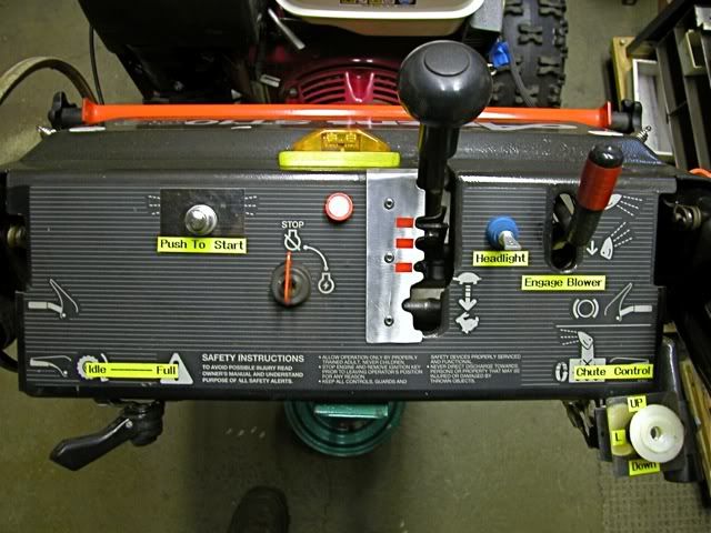
This message was modified Oct 18, 2011 by a moderator
|
jrtrebor
Location: Michigan - 3 hours north of Chicago on the lake
Joined: Feb 9, 2010
Points: 539
![]()
|
 |
Re: Ariens Project #4
Reply #25 Oct 28, 2011 5:12 pm |
|
The voltage will be the same if you measure at the B+ connection or the Solenoid+ connection. Will the voltage vary at a constant RPM? It can depending on what kind of regulator/rectifier is used. I have no idea what the IGN terminal does. Do you have a Honda part number for it? perhaps I could do a little searching for schematics using one and figure it out. From looking at a wiring diagram for the Honda tractor (HT3810) that my friend has, which is where the borrowed rectifier came from. It shows one wire coming from the rectifier going to the key switch. On it's way there is a tap off that wire going to a fuse block. The fuse block sends power to fuel pump relay, fuel pump other accessories. The B+ wire coming off the Rectifier goes to the Batt. terminal on the key switch as well. On it's way there is a tap off that wire that goes to the battery. Third terminal in that row on the Rectifier goes to ground. So I'm guessing that maybe the rectifier is designed to send different voltages out of the B+ terminal and the IGN terminal? One feed or output to the battery and one to the accessories. I have been using this wiring diagram and then looking at the tractors wiring to try and sort things out. It's the only way I knew how to do it. There are no diagrams for just my engine. Or drawings showing what the rectifier terminals are supposed to be connected to. The Honda part number for the Rectifier that is supposed to be used with my engine is 31600-ZE2-861. I verified that through Honda using all my engine codes (QNE2 & GCANK) and through another parts distributor. There is one for sale on Ebay that also verified it and showed the manufacturer and Part # Shindengen SH586B-12. The rectifier that I am borrowing is made by the same manufacturer but has a different part number SH561-12. I went to the Manufacturers web site and found the borrowed rectifier part number (SH561-12). Along with a connecting/wiring diagram for that rectifier. (I didn't see a listing for my specified rectifier. SH586B-12) I'm sure it's showing what I'd like to know, but I don't know what a lot of the symbols mean. So I don't know what it's telling me. I'm sure you would know. It's listed under Single Phase Regulator Rectifier Lineup (Full Wave)
Shunt Style Regulator MatrixThe borrowed rectifier ( SH561-12) seems to be very similar to what Honda calls for on my engine (SH586B-12). Except that the one rating is a little lower @ 8A instead of 10A. I believe that the Connecting Diagram for it is further down the page. Where it says Connecting Diagram
(Series-Shunt)
If you wouldn't mind having a look and telling me what it say's and what you think I'd appreciate it. Both rectifiers have five terminals. One row of two terminals, for the 2 coil wire hook ups. One row of three terminals, a ground wire terminal, and two voltage output terminals. Thanks everyone for your comments and help. I am lost when it comes to some of this stuff. I just don't know the basics of electronic components and what they do or how they work.
This message was modified Oct 29, 2011 by jrtrebor
|
JimmyM
Joined: Dec 19, 2009
Points: 82
![]()
|
|
|
Re: Ariens Project #4
Reply #26 Oct 31, 2011 10:30 am |
|
Well. The SH561-12 is a combination regulator and rectifier. So a simple bridge rectifier can't be substituted. The page you link to is formatted such that the diagrams shown are for the part numbers listed above them. The section for the SH561 doesn't show a diagram. The ones under it (SH734, et al) are a different type of regulator (Series vs Shunt), so their diagrams can't be used. I did some searching on SH561 but found few results. I'm going to try looking up the other part numbers and see if I can find a wiring diagram. It may be that the IGN terminal needs to be tied to B+ since your diagram shows it connected to the ignition switch. But I can't be sure. Edit: I found a wiring diagram for a water craft that uses the SH589, but it only shows 4 wires connecting to it.
This message was modified Oct 31, 2011 by JimmyM
|
JimmyM
Joined: Dec 19, 2009
Points: 82
![]()
|
|
|
Re: Ariens Project #4
Reply #28 Nov 1, 2011 4:48 am |
|
Don't know whether this was just a typo.
" Edit: I found a wiring diagram for a water craft that uses the SH589, but it only shows 4 wires connecting to it".
Should be SH586B don't know what the B stand for.
Thanks again I really appreciate your help.
Nope. Not a type-o. The SH589 is listed in the table in your link right above the SH561. I was thinking that if the others were shunt style regulators, a diagram of an SH589 might help since google hits on sh561 were few. I get a lot of Kawasaki hits when searching. I found a manual for the HT3810 on line. http://www.hondapowerequipment.com/pdf/manuals/31750713.pdfIt looks like the far left is ground, the next 2 are the coil connections, the 4th is the IGN terminal and the far right is the Battery. It may be that the IGN terminal needs to be connected to the B+ connection when running. That's the only reason I can think of that the IGN wire goes to the Ignition switch. In the diagram it also shows it (IGN) connection to the B+ feed to the fuse block lending more credence to my theory that the IGN terminal needs B+ to function when running.
This message was modified Nov 1, 2011 by JimmyM
|
jrtrebor
Location: Michigan - 3 hours north of Chicago on the lake
Joined: Feb 9, 2010
Points: 539
![]()
|
|
|
Re: Ariens Project #4
Reply #29 Nov 1, 2011 3:18 pm |
|
Nope. Not a type-o. The SH589 is listed in the table in your link right above the SH561. I was thinking that if the others were shunt style regulators, a diagram of an SH589 might help since google hits on sh561 were few. I get a lot of Kawasaki hits when searching. I found a manual for the HT3810 on line. http://www.hondapowerequipment.com/pdf/manuals/31750713.pdfIt looks like the far left is ground, the next 2 are the coil connections, the 4th is the IGN terminal and the far right is the Battery. It may be that the IGN terminal needs to be connected to the B+ connection when running. That's the only reason I can think of that the IGN wire goes to the Ignition switch. In the diagram it also shows it (IGN) connection to the B+ feed to the fuse block lending more credence to my theory that the IGN terminal needs B+ to function when running. Didn't know on the typo, thought Id ask. What could happen to the coils, rectifier etc. If the ground wire (far left) and the Battery (far right) were hooked up wrong? In others words the Battery terminal got hooked to ground and the ground terminal got hook to battery. The reason I ask is that when I look at the plug that plugs into the rectifier on the Honda tractor. The far left terminal wire is white - the center terminal wire is blk with yellow stripe - and the far right terminal wire is black. That's different than what the wiring diagram seems to show. I realize that there is really no way of knowing whether your seeing the plug from the front or back in the wiring diagram. So I have just be assuming that I should go by what I see on the tractors plug. Far left (1st) terminal Center (2nd) terminal. Far right (3rd) terminal is hooked to ground. (Battery is hooked in system). This morning when I check things again I got different readings than last night. The center 2nd terminal was putting out less than last night when I checked it. Reading off 1st terminal @ idle 14.5V........ @ full throttle 17.8V. Reading started at at 16.5V when I first made connection then built up to 17.8V Reading off 2nd terminal (center) @ idle 12.5V......... @ full throttle 12.5V Last night 13.5V idle 13.5V full T Neither set of readings seem to be optimal. The 14.5v is ok but the 17V is to high. The 12.5V would be ok but I'm not sure that the 12.5V is enough to keep the battery charged with the light on. But maybe it would be. The engine fires right up so I really don't need a whole lot from the battery. .
This message was modified Nov 2, 2011 by jrtrebor
|
jrtrebor
Location: Michigan - 3 hours north of Chicago on the lake
Joined: Feb 9, 2010
Points: 539
![]()
|
|
|
Re: Ariens Project #4
Reply #31 Nov 2, 2011 4:24 pm |
|
It doesn't make sense that the voltage in the one test was 13.5 at idle and only 12.8 at full throttle, unless the voltage regulator is sensing that the battery if full and is cutting back the charge rate. maybe try the test again with the light on. If the charge rate with the light on and the battery connected, while not the idle voltage 12.8 should still maintain the battery. Good luck
Carl carlb. I revised some of the readings that I posted in my previous post. I do get readings that seem to fluctuate not sure what that is about. I think it's time for me to end this thread or at least stop posting new information. I need to keep reminding myself that the Rectifier that I am using is off a Honda garden tractor. It has it's own electrical system. Lights,switches, relays, fuel pump, safety switches etc. That rectifier is not the correct one called for by Honda for my engine and coil combination. So expecting to see voltage number that are what I think they should be is kind foolish on my part. It's not the correct rectifier. I'm getting at least 12+ volts at idle and full throttle out of the center terminal. That should at least keep me from discharging the battery to a level below where it won't start the blower. I would hope. Running my light won't put much drain on the system. Maybe I will be able to find the correct rectifier at a price I can justify buying. Normally they are around $120.00 to $140.00. I only paid $130.00 for the engine. I've got a lawn mower junk yard about 20 miles from me. I will probably take a run by there and see what I can find. Thanks for everyone's help, I've learned somethings. Now I know enough to fill a shot glass, LOL. I'm still open to any and all comments that you knowledgeable posters may have.
|
jrtrebor
Location: Michigan - 3 hours north of Chicago on the lake
Joined: Feb 9, 2010
Points: 539
![]()
|
|
|
Re: Ariens Project #4
Reply #34 Nov 5, 2011 8:17 pm |
|
Check the battery voltage with the engine off, it should be around 12.5 12.6 volts. If you can maintain 12.5 volts with the engine running and the light on you will probably be ok. I checked the battery, it was reading 12.5V. At idle and full throttle with the light on I was getting a steady reading of 11.9V. I also disconnected both battery cables, and at both an idle and full throttle I got nothing out of the light. Not even a faint dim glow. Even the two small LED marker lights I have showed nothing. And those draw hardly any power at all. That seems odd to me. Why would the coils not be putting out enough to at least light the LEDs?? I think I need to leave the battery disconnected and start over. See what readings I get right off the rectifier terminals. Or right off the coil wires themselves. But that's AC I believe. And I'm not sure what readings to even look for, or to expect. It was easier to figure out and repower the blower than it's been to figure out this electrical stuff.,,, LOL sort of. May I should just strap a car battery to it and throw a charger on it every once in a while. This is making me crazy.
|
|
|