Abby's Guide to Outdoor Power Equipment (Lawn Mowers, Snow Blowers, Chain Saws and more)
Username Password
Discussions Reviews More Guides
Abby’s Guide > Outdoor Power Equipment (Lawn Mowers, Snow Blowers, Chain Saws and more) > Discussions > Ariens Project #4

Outdoor Power Equipment (Lawn Mowers, Snow Blowers, Chain Saws and more) Discussions

Search For:
jrtrebor


Location: Michigan - 3 hours north of Chicago on the lake
Joined: Feb 10, 2010
Points: 539

Ariens Project #4
Original Message   Oct 15, 2011 9:35 pm
Finished redoing the dash on my blower
The new Honda 13hp engine I got to repower the blower (again)
was in great shape. Has the electric start and a 10A charging coil.
But it didn't have any of the wiring. No key switch, no rectifier, nothing.
All the factory stuff is way out of my budget so It had to go old school.
With an ignition on/off switch. (The old one that was still on the blower)
And a starter push button. Which meant that I had to rewire the whole
ignition system from the engine to the dash.
That is how things got started.
Then being the way I am, I couldn't just run new wire and leave it at that.
What's the fun it that. Anyway it's finished.
Just need to get a new impeller bearing and flanges and I can put the whole blower
back together and mate it to the tractor.


This message was modified Oct 18, 2011 by a moderator
Replies: 18 - 27 of 58Next page of topicsPreviousNextNext page of topicsAllView as Outline
jrtrebor


Location: Michigan - 3 hours north of Chicago on the lake
Joined: Feb 10, 2010
Points: 539

Re: Ariens Project #4 Dash and lighting coils
Reply #18   Oct 25, 2011 12:11 pm
Well it appears that I may have somehow burned up the lighting coils or done something to them, I guess??
This morning I was going check the output again. Didn't change any of the wiring from the last
time I ran a check. Started up the engine.  Put the red wire probe on the solenoid terminal
(where I put it last time) put the black wire probe to ground. Meter showing  - 0.16V.
Unpluged the coil wires from the rectifier (took the rectifier off the engine.)
Started it up again. Red probe to one to the coil wires, black probe to ground same reading.

Hate it when this kind of stuff happens, have no idea what happened or what I might have done wrong.

  JimmyM - There are actually four wires coming from the coil(s), that are then combined to leave two
wires with connectors on the ends.  Don't understand what that's about.


This message was modified Oct 25, 2011 by jrtrebor
JimmyM


Joined: Dec 20, 2009
Points: 82

Re: Ariens Project #4 Dash and lighting coils
Reply #19   Oct 26, 2011 11:31 am
jrtrebor wrote:
Well it appears that I may have somehow burned up the lighting coils or done something to them, I guess??
This morning I was going check the output again. Didn't change any of the wiring from the last
time I ran a check. Started up the engine.  Put the red wire probe on the solenoid terminal
(where I put it last time) put the black wire probe to ground. Meter showing  - 0.16V.
Unpluged the coil wires from the rectifier (took the rectifier off the engine.)
Started it up again. Red probe to one to the coil wires, black probe to ground same reading.

Hate it when this kind of stuff happens, have no idea what happened or what I might have done wrong.

  JimmyM - There are actually four wires coming from the coil(s), that are then combined to leave two
wires with connectors on the ends.  Don't understand what that's about.


It does look a little odd, but there could be a couple of reasons.
1. Combining the outputs of a standard "dual output" coil for greater current.
2. Each of the wires going into a single wire may be a diode output so the combined output is fully rectified DC instead of just the upper or lower halves of a half-wave rectified AC wave.

But, for sure, if the wires connected directly to the solenoid (starter solenoid) the you do NOT need a rectifier and the coil is designed to connect directly to a battery since the battery would be connected to the solenoid and ground.

Silly question. Was the meter set to DC or AC?
jrtrebor


Location: Michigan - 3 hours north of Chicago on the lake
Joined: Feb 10, 2010
Points: 539

Re: Ariens Project #4
Reply #20   Oct 27, 2011 12:23 am
Well today I received the bridge rectifiers that bought on ebay.  Had to buy two, they are rated 50A - 200V.  I checked the output again after I found out that I had two wires swapped on the rectifier that
I borrowed off my friends tractor.  I had the battery+ and the ground wire swapped. Not good!! Anyway after I connected them correctly. I found I was still getting some output out of the coils.

I removed the borrowed rectifier and installed the new BR this evening.


When I took a reading at full throttle with a battery hooked in the system.  I was getting 17.8 volts. I took a reading with the
red probe on the solenoid and with it on the battery + post. Same reading. (As it should be I guess)
If I disconnected one of the coil wires from the BR the reading dropped to about 12.8V
Not really sure what to make of that?  12.8V is okay but 17.8 is still to high.
I'm just happy the coils seem to be working.  I'd run just one coil if it wouldn't hurt anything and it was putting out
enough to keep the battery charged when running my lights.  Everything I've been able to check regarding the size of the coil
on this engine (GX390U1 GCANK  QNE2) says it's supposed to have a 10A charging system. I must be missing something.
(I'm actually missing a lot when it comes to this kind of stuff, I know what things are supposed to do but I don't understand how they work).
I don't know what else to do to get the voltage down with both coils hooked up. To somewhere around 13-14V
Thoughts anyone.    Thanks for all your help JimmyM
I just reread you post. should I be connecting the BR + output wire directly to the battery instead of connecting it to the solenoid? As well
as the - / ground wire?  Is that what your saying? One wiring diagram I ran across for the OEM rectifier did show the left terminal marked as B +
The center terminal was marked Ign. and the right terminal was B-.  (Assuming B is battery and Ign is the key switch).
I haven't tried that yet.
 

This message was modified Oct 27, 2011 by jrtrebor
carlb


Joined: Nov 16, 2010
Points: 279

Re: Ariens Project #4
Reply #21   Oct 27, 2011 9:42 am
did you check to output from the coils before the rectifier to see if they were ac or dc?  If it is in fact DC you should not need the rectifier just connect the positive to the solinoid and the ground to a chassis ground and hook up the battery and then check the voltage again.

Carl
JimmyM


Joined: Dec 20, 2009
Points: 82

Re: Ariens Project #4
Reply #22   Oct 27, 2011 3:06 pm
Gee, jrtrbor, I'm not sure what to make of this. 17.8V is way too high. You should be able to connect the BR+ output to either the Battery+ or the battery side of the solenoid. If you disconnected one of the coil wires from the BR~ connections, your meter would be showing the battery voltage if the leads were connected to the BR+ and BR- outputs. The coil shouldn't be putting any power through the rectifier at that point. 12.8V sounds right for a battery that was just subjected to 17.8V.
jrtrebor


Location: Michigan - 3 hours north of Chicago on the lake
Joined: Feb 10, 2010
Points: 539

Re: Ariens Project #4
Reply #23   Oct 27, 2011 3:44 pm
This is actually getting more confusing for me by the day, LOL.  I'm not sure that I know how to correctly check for AC voltage.  Or what kind of readings to expect to see.
I thought I did but the readings I tried to take this morning seemed to be all over the place.  And the readings between the two different coil wires are quite a bit different.  I was putting black probe to ground, red probe to coil wire.  Meter in VAC mode.  I'm just trying to be careful and not do something I shouldn't and burn something up, coils, rectifiers.

I hooked up the new Bridge Rectifier had a battery connected in the system.  Meter in VDC mode.
Black probe to ground red probe to solenoid + terminal and or battery + post.    At idle reading -14.2V 
Black probe to ground red probe to solenoid + terminal and or battery + post.     Full throttle reading - 17.2V

Removed Bridge Rectifier and hooked up borrowed Honda Rectifier, battery connected in the system. 
With a wire hooked to the B + terminal (left terminal) on the Rectifier.   At idle reading - 13.5V
With a wire hooked to the B + terminal on the Rectifier.    Full throttle reading - 16.8V

Second test with Honda Rectifier
Wire was moved to the IGN. terminal (center terminal) on the Rectifier.    At idle reading - 13.2V
Full throttle reading - with the wire hooked to the IGN. terminal on the Rectifier.    Full throttle reading - 13.1V
The other end of the wire that I'm talking about above is connected to the solenoid + terminal.  There are no wires coming from either rectifier going directly to the battery.  If the wire was connected
to the battery + post instead of solenoid + terminal could and or would that change the readings?

Can, and will the output voltage from the coils vary even when the engine RPM is constant?  I guess what I get a little confused about is whether both coils are independent of each other.
 Each putting out a certain amount of voltage at a given RPM.  How and or what happens when you combine them by connecting them to the Bridge rectifier or the Honda rectifier/ regulator.
I realize explaining this may be way more involved or over my head.  I get some of it, some of it I don't.  Was hoping to learn something out of this but I seem to be getting a little more confused
than I was.  I think I've learned that a Bridge Rectifier does nothing more than change or convert AC voltage to DC voltage.
Is 13 + volts enough to keep the battery charged when I'm running my small light.  I don't recall what the wattage is, but I know it's less than 50.  And the charging coil is supposed to be 10A.
This message was modified Oct 27, 2011 by jrtrebor
JimmyM


Joined: Dec 20, 2009
Points: 82

Re: Ariens Project #4
Reply #24   Oct 28, 2011 11:23 am
The voltage will be the same if you measure at the B+ connection or the Solenoid+ connection. Will the voltage vary at a constant RPM? It can depending on what kind of regulator/rectifier is used. I have no idea what the IGN terminal does. Do you have a Honda part number for it? perhaps I could do a little searching for schematics using one and figure it out.
jrtrebor


Location: Michigan - 3 hours north of Chicago on the lake
Joined: Feb 10, 2010
Points: 539

Re: Ariens Project #4
Reply #25   Oct 28, 2011 9:12 pm
JimmyM wrote:
The voltage will be the same if you measure at the B+ connection or the Solenoid+ connection. Will the voltage vary at a constant RPM? It can depending on what kind of regulator/rectifier is used. I have no idea what the IGN terminal does. Do you have a Honda part number for it? perhaps I could do a little searching for schematics using one and figure it out.

From looking at a wiring diagram for the Honda tractor (HT3810) that my friend has, which is where the borrowed rectifier came from.  It shows one wire coming from the rectifier going to the key switch.
On it's way there is a tap off that wire going to a fuse block.  The fuse block sends power to fuel pump relay, fuel pump other accessories.  The B+ wire coming off the Rectifier goes to the Batt. terminal
on the key switch as well. On it's way there is a tap off that wire that goes to the battery. Third terminal in that row on the Rectifier goes to ground.

So I'm guessing that maybe the rectifier is designed to send different voltages out of the B+ terminal and the IGN terminal?  One feed or output to the battery and one to the accessories.
I have been using this wiring diagram and then looking at the tractors wiring to try and sort things out.  It's the only way I knew how to do it.  There are no diagrams for just my engine.
Or drawings showing what the rectifier terminals are supposed to be connected to.

The Honda part number for the Rectifier that is supposed to be used with my engine is 31600-ZE2-861. I verified that through Honda using all my engine codes (QNE2 & GCANK) and through
another parts distributor.  There is one for sale on Ebay that also verified it and showed the manufacturer and Part #  Shindengen SH586B-12.
The rectifier that I am borrowing is made by the same manufacturer but has a different part number SH561-12.  I went to the Manufacturers web site and found the borrowed rectifier part number (SH561-12).  
Along with a connecting/wiring diagram for that rectifier.  (I didn't see a listing for my specified rectifier. SH586B-12)
I'm sure it's showing what I'd like to know, but I don't know what a lot of the symbols mean. So I don't know what it's telling me.  I'm sure you would know. 
It's listed under
Single Phase Regulator Rectifier Lineup (Full Wave)
Shunt Style Regulator Matrix

The borrowed rectifier ( SH561-12) seems to be very similar to what Honda calls for on my engine (SH586B-12).  Except that the one rating is a little lower @ 8A instead of 10A.
I believe that the Connecting Diagram for it is further down the page.  Where it says
Connecting Diagram
(Series-Shunt)

If you wouldn't mind having a look and telling me what it say's and what you think I'd appreciate it.
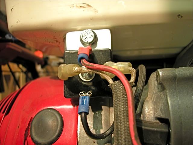
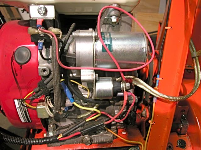
Both rectifiers have five terminals. One row of two terminals, for the 2 coil wire hook ups.  One row of three terminals, a ground wire terminal, and two voltage output terminals.
Thanks everyone for your comments and help. I am lost when it comes to some of this stuff. I just don't know the basics of electronic components and what they do or how they work.


This message was modified Oct 29, 2011 by jrtrebor
JimmyM


Joined: Dec 20, 2009
Points: 82

Re: Ariens Project #4
Reply #26   Oct 31, 2011 2:30 pm
Well. The SH561-12 is a combination regulator and rectifier. So a simple bridge rectifier can't be substituted.
The page you link to is formatted such that the diagrams shown are for the part numbers listed above them. The section for the SH561 doesn't show a diagram. The ones under it (SH734, et al) are a different type of regulator (Series vs Shunt), so their diagrams can't be used.
I did some searching on SH561 but found few results. I'm going to try looking up the other part numbers and see if I can find a wiring diagram. It may be that the IGN terminal needs to be tied to B+ since your diagram shows it connected to the ignition switch. But I can't be sure.

Edit: I found a wiring diagram for a water craft that uses the SH589, but it only shows 4 wires connecting to it.
This message was modified Oct 31, 2011 by JimmyM
jrtrebor


Location: Michigan - 3 hours north of Chicago on the lake
Joined: Feb 10, 2010
Points: 539

Re: Ariens Project #4
Reply #27   Oct 31, 2011 4:02 pm
Thanks for taking a look.  If I could get my friend to sell me his tractor I could plan on using the SH561 that I'm borrowing.  I guess?  From what I could make out from the spec sheets it looked like it might be a little
under rated (8A) for my 10A coils.  But I'm not sure whether that would really make any difference.  I'm never going to have anything on the blower that would pull a constant 10A or even close to that.  Keeping the battery charged, running the small I believe 25W light and maybe running my chute control motors.  But they draw very little as well, and it's just a momentary draw.
 I have a wiring diagram for the Honda tractor (HT3810) that the SH561 Rec. came off of.  But the scan of the diagram was so poor that it's hard to make out things out, it's just not a clear and sharp diagram.
It also doesn"t show exactly what terminal are what on the rectifier. It just shows five wire in a row and where they are routed to.  Not much help.

Don't know whether this was just a typo.
" Edit: I found a wiring diagram for a water craft that uses the SH589, but it only shows 4 wires connecting to it".
Should be SH586B don't know what the B stand for.
Thanks again I really appreciate your help.
Replies: 18 - 27 of 58Next page of topicsPreviousNextNext page of topicsAllView as Outline
Outdoor Power Equipment (Lawn Mowers, Snow Blowers, Chain Saws and more) Guide   •   Discussions  Reviews  
AbbysGuide.com   About Us   Terms of Use   Privacy Policy   Contact Us
Copyright 1998-2024 AbbysGuide.com. All rights reserved.
Site by Take 42