Abby’s Guide > Outdoor Power Equipment (Lawn Mowers, Snow Blowers, Chain Saws and more) > Discussions > Ariens Project #4
Outdoor Power Equipment (Lawn Mowers, Snow Blowers, Chain Saws and more) Discussions |
|
jrtrebor
 
Location: Michigan - 3 hours north of Chicago on the lake
Joined: Feb 9, 2010
Points: 539
![]()
|
 |
Ariens Project #4
Original Message Oct 15, 2011 5:35 pm |
|
Finished redoing the dash on my blower The new Honda 13hp engine I got to repower the blower (again) was in great shape. Has the electric start and a 10A charging coil. But it didn't have any of the wiring. No key switch, no rectifier, nothing. All the factory stuff is way out of my budget so It had to go old school. With an ignition on/off switch. (The old one that was still on the blower) And a starter push button. Which meant that I had to rewire the whole ignition system from the engine to the dash. That is how things got started. Then being the way I am, I couldn't just run new wire and leave it at that. What's the fun it that. Anyway it's finished. Just need to get a new impeller bearing and flanges and I can put the whole blower back together and mate it to the tractor.  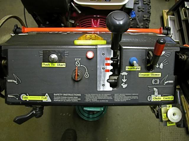
This message was modified Oct 18, 2011 by a moderator
|
JimmyM
Joined: Dec 19, 2009
Points: 82
![]()
|
 |
Re: Ariens Project #4
Reply #13 Oct 21, 2011 1:42 pm |
|
Thats 6 amps at 50 volts or to use a common unit of measure 300 watts.
A load of 10 amps at 12Volts is only 120watts.
The 6amp 50 volt will easily handle the 10 amps at 12vdc.
and yes as i said larger ones are available for penny's more. By that rationale, I could put 10V and 25A though it. Right? or 1A at 250V. In either of those scenarios, the rectifier WILL fail. The 300W would only be relevant to power dissipation. You can still only put 6A through each diode. And 50V is the PIV rating. Any more than 50V PIV and the diode fails. You cannot exceed EITHER rating. Spend the extra $$$ and get a diode that exceeds both your requirements. A much greater PIV is more important to hedge against voltage spikes.
|
JimmyM
Joined: Dec 19, 2009
Points: 82
![]()
|
|
|
Re: Ariens Project #4
Reply #15 Oct 22, 2011 9:48 am |
|
Thanks for the comments.
carlb - When I hooked up a battery to the system today. The voltage did come down to right around 12.5V at a high RPM. Remove the battery and I show about 40V at the same RPM.
Question, should the rectifier be getting warm almost a little hot?
Also JimmyM the link to the rectifier on ebay that you posted. I've seen one like that before. Two terminals used for AC input from coil. One terminal to battery+ or + terminal on starter solenoid.
One terminal to ground, Yes? Will I need a voltage regulator with that rectifier? I don't want to boil the battery. Should I use a heat sink behind the rectifier?
Sorry to ask so many questions. I'd like to get it right and also learn something in the process. You shouldn't need a heatsink. If you use a screw or bolt to secure it. It should be fine. It will only need a heatsink if you are using it at or near its capacity. The AC (~) terminals are pretty easy to connect. Typically you'll connect one to the charging coil output and the other to the engine block. If your coil has 2 outputs, connect one wire to each AC terminal. The open circuit voltage is going top be pretty high. But it only really matters what the voltage is under load. Hook up a 12V automotive bulb to the (+) and (-) connections of the rectifier and see what happens. The bulb may burnout. If you connect your battery to the rectifier output + to +, - to - the bulb won't blow, but the battery voltage should NEVER go over 14.5V. But let's keep in mind that these charging coils are used for this exact purpose. Also, if your charging coil has only one wire, do NOT connect the (-) output of the rectifier to the frame as a "ground". A voltage regulator is a bit tougher to talk about. If you add a voltage regulator to this, it won't be like a typical voltage regulator in a car. The one in a car controls the alternator to keep output at about 13.5V. The one you would have to install would not be controlling the charging coil, but simply reducing its output voltage like a self adjusting resistor. It would have to dissipate heat. So at, for example, 17V from the rectifier, and 13V output, you need to drop 4V. At 6A, that means you have to dissipate 24W of power as heat. You can solder with 20W. So that regulator will get plenty hot. Try the battery and bulb approach first.
|
jrtrebor
Location: Michigan - 3 hours north of Chicago on the lake
Joined: Feb 9, 2010
Points: 539
![]()
|
|
|
Re: Ariens Project #4
Reply #16 Oct 22, 2011 10:50 am |
|
You shouldn't need a heatsink. If you use a screw or bolt to secure it. It should be fine. It will only need a heatsink if you are using it at or near its capacity.
The AC (~) terminals are pretty easy to connect. Typically you'll connect one to the charging coil output and the other to the engine block. If your coil has 2 outputs, connect one wire to each AC terminal. The open circuit voltage is going top be pretty high.
But it only really matters what the voltage is under load. Hook up a 12V automotive bulb to the (+) and (-) connections of the rectifier and see what happens. The bulb may burnout. If you connect your battery to the rectifier output + to +, - to - the bulb won't blow, but the battery voltage should NEVER go over 14.5V. But let's keep in mind that these charging coils are used for this exact purpose. Also, if your charging coil has only one wire, do NOT connect the (-) output of the rectifier to the frame as a "ground".
A voltage regulator is a bit tougher to talk about. If you add a voltage regulator to this, it won't be like a typical voltage regulator in a car. The one in a car controls the alternator to keep output at about 13.5V. The one you would have to install would not be controlling the charging coil, but simply reducing its output voltage like a self adjusting resistor. It would have to dissipate heat. So at, for example, 17V from the rectifier, and 13V output, you need to drop 4V. At 6A, that means you have to dissipate 24W of power as heat. You can solder with 20W. So that regulator will get plenty hot.
Try the battery and bulb approach first. Thanks for your response. I do have two wires coming from the coil. I understand what you're saying about the car regulator actually controlling the output of the alt. Where as the coil on my engine simply puts out what ever it puts out at any given RPM. My only real concern in this is not sending too much voltage to the battery. I will be running lights when I need them. But the rest of the time the battery will only be used for starting the blower. The 11hp Honda clone I was using had a 3A coil but it didn't seem to put out enough to keep the battery charged when I was running the light for an hour or two. I'm sure I won't have that problem with this coil. I'm going to run another check to make sure that when I have the battery hooked into the system. With the engine running full throttle that the voltage stays some where between 12.5 and 14.5V. I guess if I see that, that I'm good to go with buying and installing that rectifier on Ebay. Any other things that I should know?
This message was modified Oct 22, 2011 by jrtrebor
|
JimmyM
Joined: Dec 19, 2009
Points: 82
![]()
|
|
|
Re: Ariens Project #4
Reply #17 Oct 24, 2011 5:21 am |
|
Thanks for your response. I do have two wires coming from the coil. I understand what you're saying about the car regulator actually controlling the output of the alt. Where as the coil on my engine simply
puts out what ever it puts out at any given RPM. My only real concern in this is not sending too much voltage to the battery. I will be running lights when I need them. But the rest of the time the battery will
only be used for starting the blower. The 11hp Honda clone I was using had a 3A coil but it didn't seem to put out enough to keep the battery charged when I was running the light for an hour or two.
I'm sure I won't have that problem with this coil. I'm going to run another check to make sure that when I have the battery hooked into the system. With the engine running full throttle that the voltage stays
some where between 12.5 and 14.5V. I guess if I see that, that I'm good to go with buying and installing that rectifier on Ebay. Any other things that I should know? Hang on. If the coil is designed to be connected directly to a battery, then it's not putting out AC, it's just unfiltered DC. Which is fine for light bulbs and for batteries. What do you think the alternator in your car puts out? Unfiltered DC. In fact, the battery IS the filter for the rest of the car's DC systems. Do you have a volt meter? If so, set it to DC and read the voltage off the coil wires. If you get a positive voltage one way and a negative voltage the other way. Skip the rectifier and just connect the battery and light. You're good to go. Actually, you'll find a lot of articles that say pulsating DC is better than straight DC for charging lead/acid batteries because it reduces sulfation. OF course, the RMS voltage should still remain in the recommended 12.5 (low float) to 14.5V (absorption phase) range.
This message was modified Oct 24, 2011 by JimmyM
|
jrtrebor
Location: Michigan - 3 hours north of Chicago on the lake
Joined: Feb 9, 2010
Points: 539
![]()
|
|
|
Re: Ariens Project #4 Dash and lighting coils
Reply #18 Oct 25, 2011 8:11 am |
|
Well it appears that I may have somehow burned up the lighting coils or done something to them, I guess?? This morning I was going check the output again. Didn't change any of the wiring from the last time I ran a check. Started up the engine. Put the red wire probe on the solenoid terminal (where I put it last time) put the black wire probe to ground. Meter showing - 0.16V. Unpluged the coil wires from the rectifier (took the rectifier off the engine.) Started it up again. Red probe to one to the coil wires, black probe to ground same reading. Hate it when this kind of stuff happens, have no idea what happened or what I might have done wrong. JimmyM - There are actually four wires coming from the coil(s), that are then combined to leave two wires with connectors on the ends. Don't understand what that's about. 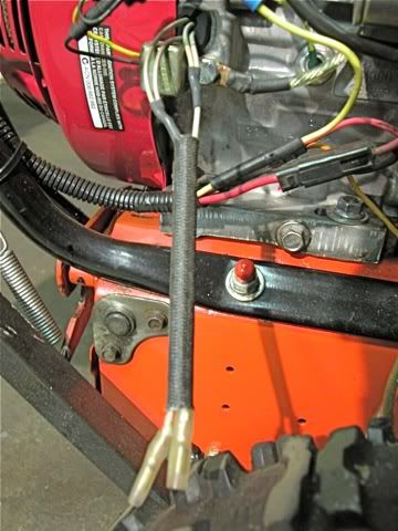
This message was modified Oct 25, 2011 by jrtrebor
|
JimmyM
Joined: Dec 19, 2009
Points: 82
![]()
|
|
|
Re: Ariens Project #4 Dash and lighting coils
Reply #19 Oct 26, 2011 7:31 am |
|
Well it appears that I may have somehow burned up the lighting coils or done something to them, I guess??
This morning I was going check the output again. Didn't change any of the wiring from the last
time I ran a check. Started up the engine. Put the red wire probe on the solenoid terminal
(where I put it last time) put the black wire probe to ground. Meter showing - 0.16V.
Unpluged the coil wires from the rectifier (took the rectifier off the engine.)
Started it up again. Red probe to one to the coil wires, black probe to ground same reading.
Hate it when this kind of stuff happens, have no idea what happened or what I might have done wrong.
JimmyM - There are actually four wires coming from the coil(s), that are then combined to leave two
wires with connectors on the ends. Don't understand what that's about.
It does look a little odd, but there could be a couple of reasons. 1. Combining the outputs of a standard "dual output" coil for greater current. 2. Each of the wires going into a single wire may be a diode output so the combined output is fully rectified DC instead of just the upper or lower halves of a half-wave rectified AC wave. But, for sure, if the wires connected directly to the solenoid (starter solenoid) the you do NOT need a rectifier and the coil is designed to connect directly to a battery since the battery would be connected to the solenoid and ground. Silly question. Was the meter set to DC or AC?
|
jrtrebor
Location: Michigan - 3 hours north of Chicago on the lake
Joined: Feb 9, 2010
Points: 539
![]()
|
|
|
Re: Ariens Project #4
Reply #20 Oct 26, 2011 8:23 pm |
|
Well today I received the bridge rectifiers that bought on ebay. Had to buy two, they are rated 50A - 200V. I checked the output again after I found out that I had two wires swapped on the rectifier that I borrowed off my friends tractor. I had the battery+ and the ground wire swapped. Not good!! Anyway after I connected them correctly. I found I was still getting some output out of the coils. I removed the borrowed rectifier and installed the new BR this evening. 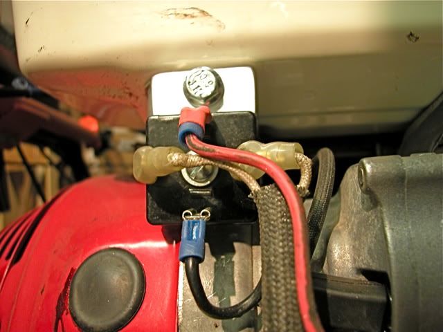 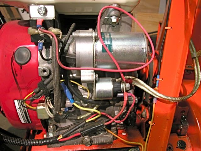 When I took a reading at full throttle with a battery hooked in the system. I was getting 17.8 volts. I took a reading with the red probe on the solenoid and with it on the battery + post. Same reading. (As it should be I guess) If I disconnected one of the coil wires from the BR the reading dropped to about 12.8V Not really sure what to make of that? 12.8V is okay but 17.8 is still to high. I'm just happy the coils seem to be working. I'd run just one coil if it wouldn't hurt anything and it was putting out enough to keep the battery charged when running my lights. Everything I've been able to check regarding the size of the coil on this engine (GX390U1 GCANK QNE2) says it's supposed to have a 10A charging system. I must be missing something. (I'm actually missing a lot when it comes to this kind of stuff, I know what things are supposed to do but I don't understand how they work). I don't know what else to do to get the voltage down with both coils hooked up. To somewhere around 13-14V Thoughts anyone. Thanks for all your help JimmyM I just reread you post. should I be connecting the BR + output wire directly to the battery instead of connecting it to the solenoid? As well as the - / ground wire? Is that what your saying? One wiring diagram I ran across for the OEM rectifier did show the left terminal marked as B + The center terminal was marked Ign. and the right terminal was B-. (Assuming B is battery and Ign is the key switch). I haven't tried that yet. 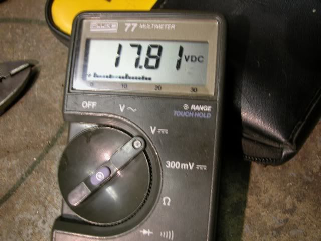
This message was modified Oct 26, 2011 by jrtrebor
|
|
|