Abby’s Guide > Outdoor Power Equipment (Lawn Mowers, Snow Blowers, Chain Saws and more) > Discussions > Ariens Project #4
Outdoor Power Equipment (Lawn Mowers, Snow Blowers, Chain Saws and more) Discussions |
|
jrtrebor
 
Location: Michigan - 3 hours north of Chicago on the lake
Joined: Feb 10, 2010
Points: 539
![]()
|
 |
Ariens Project #4
Original Message Oct 15, 2011 9:35 pm |
|
Finished redoing the dash on my blower The new Honda 13hp engine I got to repower the blower (again) was in great shape. Has the electric start and a 10A charging coil. But it didn't have any of the wiring. No key switch, no rectifier, nothing. All the factory stuff is way out of my budget so It had to go old school. With an ignition on/off switch. (The old one that was still on the blower) And a starter push button. Which meant that I had to rewire the whole ignition system from the engine to the dash. That is how things got started. Then being the way I am, I couldn't just run new wire and leave it at that. What's the fun it that. Anyway it's finished. Just need to get a new impeller bearing and flanges and I can put the whole blower back together and mate it to the tractor.  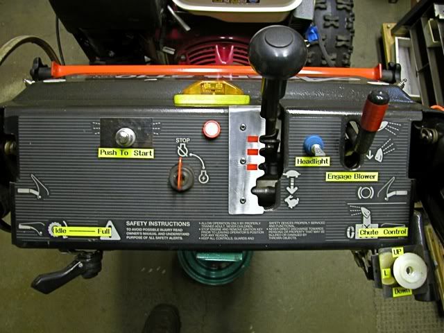
This message was modified Oct 18, 2011 by a moderator
|
JimmyM
Joined: Dec 20, 2009
Points: 82
![]()
|
 |
Re: Ariens Project #4
Reply #6 Oct 18, 2011 2:20 pm |
|
Here is a link to a small bridge rectifier on Ebay.Ā It is rated at 6amps at 50 volts or 300 watts.Ā your altenator should be putting out around 150 watts max.Ā You can buy much larger rectifiers if you have the space to mount for just penny's more. A bridge rectifier is a 4 pole device that takes in AC voltages and rectifies it to Dc voltage.ĀĀ AC in DC out.
http://www.ebay.com/itm/2-pcs-Diode-Bridge-Rectifier-RS601-6-Amps-50-V-piv-/160599857647?_trksid=p5197.m263&_trkparms=algo%3DSIC%26itu%3DUCI%252BIA%252BUA%252BFICS%252BUFI%252BDDSIC%26otn%3D12%26pmod%3D160581202605%252B300554883208%26po%3DLVI%26ps%3D63%26clkid%3D3518189249250848288 That's 6A MAX at 50V MAX. 10A will kill it. The internal Diodes are rated for only 6A each. You need a bridge rectifier rated for a minimum of 10A. Here's a nice one that will handle everything you can throw at it, has nice terminals for blade connectors and a central hole for bolting it to the bottom of your dash or where ever. http://www.ebay.com/itm/2-20A-1000V-Metal-Case-Bridge-Rectifier-SEP-KBPC2010-/120768921130?pt=LH_DefaultDomain_0&hash=item1c1e637e2a
|
carlb
Joined: Nov 16, 2010
Points: 279
![]()
|
|
|
Re: Ariens Project #4
Reply #7 Oct 18, 2011 3:40 pm |
|
Thats 6 amps at 50 volts or to use a commonĀ unit of measure 300 watts. A load of 10 amps at 12Volts is only 120watts. The 6amp 50 volt will easily handle the 10 amps at 12vdc. and yes as i said larger ones are available for penny's more.
This message was modified Oct 18, 2011 by carlb
|
JimmyM
Joined: Dec 20, 2009
Points: 82
![]()
|
|
|
Re: Ariens Project #4
Reply #13 Oct 21, 2011 5:42 pm |
|
Thats 6 amps at 50 volts or to use a commonĀ unit of measure 300 watts.
A load of 10 amps at 12Volts is only 120watts.
The 6amp 50 volt will easily handle the 10 amps at 12vdc.
and yes as i said larger ones are available for penny's more. By that rationale, I could put 10V and 25A though it. Right? or 1A at 250V. In either of those scenarios, the rectifier WILL fail. The 300W would only be relevant to power dissipation. You can still only put 6A through each diode. And 50V is the PIV rating. Any more than 50V PIV and the diode fails. You cannot exceed EITHER rating. Spend the extra $$$ and get a diode that exceeds both your requirements. A much greater PIV is more important to hedge against voltage spikes.
|
JimmyM
Joined: Dec 20, 2009
Points: 82
![]()
|
|
|
Re: Ariens Project #4
Reply #15 Oct 22, 2011 1:48 pm |
|
Thanks for the comments.Ā
carlb - When I hooked up a battery to the system today.Ā The voltage did come down to right around 12.5V at a high RPM. Remove the battery and I show about 40V at the same RPM.
Question, should the rectifier be getting warm almost a little hot?Ā
Also JimmyMĀ the link to the rectifier on ebay that you posted. I've seen one like that before.Ā Two terminals used for AC input from coil. One terminal to battery+ or + terminal on starter solenoid.
One terminal to ground, Yes?Ā Will I need a voltage regulator with that rectifier? I don't want to boil the battery.Ā Should I use a heat sink behind the rectifier?
Sorry to ask so many questions. I'd like to get it right and also learn something in the process. You shouldn't need a heatsink. If you use a screw or bolt to secure it. It should be fine. It will only need a heatsink if you are using it at or near its capacity. The AC (~) terminals are pretty easy to connect. Typically you'll connect one to the charging coil output and the other to the engine block. If your coil has 2 outputs, connect one wire to each AC terminal. The open circuit voltage is going top be pretty high. But it only really matters what the voltage is under load. Hook up a 12V automotive bulb to the (+) and (-) connections of the rectifier and see what happens. The bulb may burnout. If you connect your battery to the rectifier output + to +,Ā - to - the bulb won't blow, but the battery voltage should NEVER go over 14.5V. But let's keep in mind that these charging coils are used for this exact purpose. Also, if your charging coil has only one wire, do NOT connect the (-) output of the rectifier to the frame as a "ground". A voltage regulator is a bit tougher to talk about. If you add a voltage regulator to this, it won't be like a typical voltage regulator in a car. The one in a car controls the alternator to keep output at about 13.5V. The one you would have to install would not be controlling the charging coil, but simply reducing its output voltage like a self adjusting resistor. It would have to dissipate heat. So at, for example, 17V from the rectifier, and 13V output, you need to drop 4V. At 6A, that means you have to dissipate 24W of power as heat. You can solder with 20W. So that regulator will get plenty hot. Try the battery and bulb approach first.
|
jrtrebor
Location: Michigan - 3 hours north of Chicago on the lake
Joined: Feb 10, 2010
Points: 539
![]()
|
|
|
Re: Ariens Project #4
Reply #16 Oct 22, 2011 2:50 pm |
|
You shouldn't need a heatsink. If you use a screw or bolt to secure it. It should be fine. It will only need a heatsink if you are using it at or near its capacity.
The AC (~) terminals are pretty easy to connect. Typically you'll connect one to the charging coil output and the other to the engine block. If your coil has 2 outputs, connect one wire to each AC terminal. The open circuit voltage is going top be pretty high.
But it only really matters what the voltage is under load. Hook up a 12V automotive bulb to the (+) and (-) connections of the rectifier and see what happens. The bulb may burnout. If you connect your battery to the rectifier output + to +,Ā - to - the bulb won't blow, but the battery voltage should NEVER go over 14.5V. But let's keep in mind that these charging coils are used for this exact purpose. Also, if your charging coil has only one wire, do NOT connect the (-) output of the rectifier to the frame as a "ground".
A voltage regulator is a bit tougher to talk about. If you add a voltage regulator to this, it won't be like a typical voltage regulator in a car. The one in a car controls the alternator to keep output at about 13.5V. The one you would have to install would not be controlling the charging coil, but simply reducing its output voltage like a self adjusting resistor. It would have to dissipate heat. So at, for example, 17V from the rectifier, and 13V output, you need to drop 4V. At 6A, that means you have to dissipate 24W of power as heat. You can solder with 20W. So that regulator will get plenty hot.
Try the battery and bulb approach first. Thanks for your response.Ā I do have two wires coming from the coil.Ā I understand what you're saying about the car regulator actually controlling the output of the alt.Ā Where as the coil on my engine simply puts out what ever it puts out at any given RPM. My only real concern in this is not sending too much voltage to the battery.Ā I will be running lights when I need them.Ā But the rest of the time the battery will only be used for starting the blower.Ā The 11hp Honda clone I was using had a 3A coil but it didn't seem to put out enough to keep the battery charged when I was running the light for an hour or two. I'm sure I won't have that problem with this coil. I'm going to run another check to make sure that when I have the battery hooked into the system.Ā With the engine running full throttle that the voltage stays some where between 12.5 and 14.5V.Ā I guess if I see that, that I'm good to go with buying and installing that rectifier on Ebay.Ā Any other things that I should know?
This message was modified Oct 22, 2011 by jrtrebor
|
JimmyM
Joined: Dec 20, 2009
Points: 82
![]()
|
|
|
Re: Ariens Project #4
Reply #17 Oct 24, 2011 9:21 am |
|
Thanks for your response.Ā I do have two wires coming from the coil.Ā I understand what you're saying about the car regulator actually controlling the output of the alt.Ā Where as the coil on my engine simply
puts out what ever it puts out at any given RPM. My only real concern in this is not sending too much voltage to the battery.Ā I will be running lights when I need them.Ā But the rest of the time the battery will
only be used for starting the blower.Ā The 11hp Honda clone I was using had a 3A coil but it didn't seem to put out enough to keep the battery charged when I was running the light for an hour or two.
I'm sure I won't have that problem with this coil. I'm going to run another check to make sure that when I have the battery hooked into the system.Ā With the engine running full throttle that the voltage stays
some where between 12.5 and 14.5V.Ā I guess if I see that, that I'm good to go with buying and installing that rectifier on Ebay.Ā Any other things that I should know? Hang on. If the coil is designed to be connected directly to a battery, then it's not putting out AC, it's just unfiltered DC. Which is fine for light bulbs and for batteries. What do you think the alternator in your car puts out? Unfiltered DC. In fact, the battery IS the filter for the rest of the car's DC systems. Do you have a volt meter? If so, set it to DC and read the voltage off the coil wires. If you get a positive voltage one way and a negative voltage the other way. Skip the rectifier and just connect the battery and light. You're good to go. Actually, you'll find a lot of articles that say pulsating DC is better than straight DC for charging lead/acid batteries because it reduces sulfation. OF course, the RMS voltage should still remain in the recommended 12.5 (low float) to 14.5V (absorption phase) range.
This message was modified Oct 24, 2011 by JimmyM
|
jrtrebor
Location: Michigan - 3 hours north of Chicago on the lake
Joined: Feb 10, 2010
Points: 539
![]()
|
|
|
Re: Ariens Project #4 Dash and lighting coils
Reply #18 Oct 25, 2011 12:11 pm |
|
Well it appears that I may have somehow burned up the lighting coils or done something to them, I guess?? This morning I was going check the output again. Didn't change any of the wiring from the last time I ran a check. Started up the engine.Ā Put the red wire probe on the solenoid terminal (where I put it last time) put the black wire probe to ground. Meter showingĀ - 0.16V. Unpluged the coil wires from the rectifier (took the rectifier off the engine.) Started it up again. Red probe to one to the coil wires, black probe to ground same reading. Hate it when this kind of stuff happens, have no idea what happened or what I might have done wrong. Ā JimmyM - There are actually four wires coming from the coil(s), that are then combined to leave two wires with connectors on the ends.Ā Don't understand what that's about. 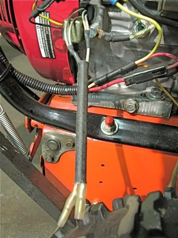
This message was modified Oct 25, 2011 by jrtrebor
|
JimmyM
Joined: Dec 20, 2009
Points: 82
![]()
|
|
|
Re: Ariens Project #4 Dash and lighting coils
Reply #19 Oct 26, 2011 11:31 am |
|
Well it appears that I may have somehow burned up the lighting coils or done something to them, I guess??
This morning I was going check the output again. Didn't change any of the wiring from the last
time I ran a check. Started up the engine.Ā Put the red wire probe on the solenoid terminal
(where I put it last time) put the black wire probe to ground. Meter showingĀ - 0.16V.
Unpluged the coil wires from the rectifier (took the rectifier off the engine.)
Started it up again. Red probe to one to the coil wires, black probe to ground same reading.
Hate it when this kind of stuff happens, have no idea what happened or what I might have done wrong.
Ā JimmyM - There are actually four wires coming from the coil(s), that are then combined to leave two
wires with connectors on the ends.Ā Don't understand what that's about.
It does look a little odd, but there could be a couple of reasons. 1. Combining the outputs of a standard "dual output" coil for greater current. 2. Each of the wires going into a single wire may be a diode output so the combined output is fully rectified DC instead of just the upper or lower halves of a half-wave rectified AC wave. But, for sure, if the wires connected directly to the solenoid (starter solenoid) the you do NOT need a rectifier and the coil is designed to connect directly to a battery since the battery would be connected to the solenoid and ground. Silly question. Was the meter set to DC or AC?
|
jrtrebor
Location: Michigan - 3 hours north of Chicago on the lake
Joined: Feb 10, 2010
Points: 539
![]()
|
|
|
Re: Ariens Project #4
Reply #20 Oct 27, 2011 12:23 am |
|
Well today I received the bridge rectifiers that bought on ebay.Ā Had to buy two, they are rated 50A - 200V.Ā I checked the output again after I found out that I had two wires swapped on the rectifier that I borrowed off my friends tractor.Ā I had the battery+ and the ground wire swapped. Not good!! Anyway after I connected them correctly. I found I was still getting some output out of the coils. I removed the borrowed rectifier and installed the new BR this evening. 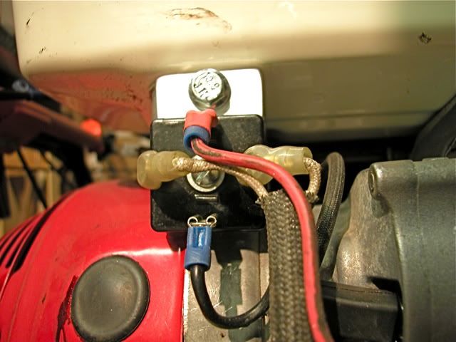 Ā 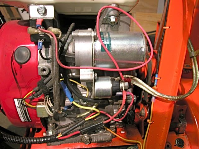 When I took a reading at full throttle with a battery hooked in the system.Ā I was getting 17.8 volts. I took a reading with the red probe on the solenoid and with it on the battery + post. Same reading. (As it should be I guess) If I disconnected one of the coil wires from the BR the reading dropped to about 12.8V Not really sure what to make of that?Ā 12.8V is okay but 17.8 is still to high. I'm just happy the coils seem to be working.Ā I'd run just one coil if it wouldn't hurt anything and it was putting out enough to keep the battery charged when running my lights.Ā Everything I've been able to check regarding the size of the coil on this engine (GX390U1 GCANKĀ QNE2) says it's supposed to have a 10A charging system. I must be missing something. (I'm actually missing a lot when it comes to this kind of stuff, I know what things are supposed to do but I don't understand how they work). I don't know what else to do to get the voltage down with both coils hooked up. To somewhere around 13-14V Thoughts anyone. ĀĀ Thanks for all your help JimmyM I just reread you post. should I be connecting the BR + output wire directly to the battery instead of connecting it to the solenoid? As well as the - / ground wire?Ā Is that what your saying? One wiring diagram I ran across for the OEM rectifier did show the left terminal marked as B + The center terminal was marked Ign. and the right terminal was B-.Ā (Assuming B is battery and Ign is the key switch). I haven't tried that yet. Ā 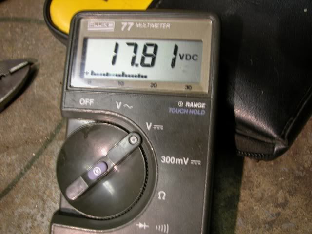
This message was modified Oct 27, 2011 by jrtrebor
|
jrtrebor
Location: Michigan - 3 hours north of Chicago on the lake
Joined: Feb 10, 2010
Points: 539
![]()
|
|
|
Re: Ariens Project #4
Reply #23 Oct 27, 2011 3:44 pm |
|
This is actually getting more confusing for me by the day, LOL.Ā I'm not sure that I know how to correctly check for AC voltage.Ā Or what kind of readings to expect to see. I thought I did but the readings I tried to take this morning seemed to be all over the place.Ā And the readings between the two different coil wires are quite a bit different.Ā I was putting black probe to ground, red probe to coil wire.Ā Meter in VAC mode.Ā I'm just trying to be careful and not do something I shouldn't and burn something up, coils, rectifiers. I hooked up the new Bridge Rectifier had a battery connected in the system.Ā Meter in VDC mode. Black probe to ground red probe to solenoid + terminal and or battery + post. ĀĀ At idle reading -14.2VĀ Black probe to ground red probe to solenoid + terminal and or battery + post. ĀĀĀ Full throttle reading - 17.2V Removed Bridge Rectifier and hooked up borrowed Honda Rectifier, battery connected in the system.Ā With a wire hooked to the B + terminal (left terminal) on the Rectifier. Ā At idle reading - 13.5V With a wire hooked to the B + terminal on the Rectifier.ĀĀĀ Full throttle reading - 16.8V Second test with Honda RectifierWire was moved to the IGN. terminal (center terminal) on the Rectifier.ĀĀĀ At idle reading - 13.2V Full throttle reading - with the wire hooked to the IGN. terminal on the Rectifier.ĀĀĀ Full throttle reading - 13.1V The other end of the wire that I'm talking about above is connected to the solenoid + terminal.Ā There are no wires coming from either rectifier going directly to the battery.Ā If the wire was connected to the battery + post instead of solenoid + terminal could and or would that change the readings? Can, and will the output voltage from the coils vary even when the engine RPM is constant?Ā I guess what I get a little confused about is whether both coils are independent of each other. ĀEach putting out a certain amount of voltage at a given RPM.Ā How and or what happens when you combine them by connecting them to the Bridge rectifier or the Honda rectifier/ regulator. I realize explaining this may be way more involved or over my head.Ā I get some of it, some of it I don't.Ā Was hoping to learn something out of this but I seem to be getting a little more confused than I was.Ā I think I've learned that a Bridge Rectifier does nothing more than change or convert AC voltage to DC voltage. Is 13 + volts enough to keep the battery charged when I'm running my small light.Ā I don't recall what the wattage is, but I know it's less than 50.Ā And the charging coil is supposed to be 10A.
This message was modified Oct 27, 2011 by jrtrebor
|
jrtrebor
Location: Michigan - 3 hours north of Chicago on the lake
Joined: Feb 10, 2010
Points: 539
![]()
|
|
|
Re: Ariens Project #4
Reply #25 Oct 28, 2011 9:12 pm |
|
The voltage will be the same if you measure at the B+ connection or the Solenoid+ connection. Will the voltage vary at a constant RPM? It can depending on what kind of regulator/rectifier is used. I have no idea what the IGN terminal does. Do you have a Honda part number for it? perhaps I could do a little searching for schematics using one and figure it out. From looking at a wiring diagram for the Honda tractor (HT3810) that my friend has, which is where the borrowed rectifier came from.Ā It shows one wire coming from the rectifier going to the key switch. On it's way there is a tap off that wire going to a fuse block.Ā The fuse block sends power to fuel pump relay, fuel pump other accessories.Ā The B+ wire coming off the Rectifier goes to the Batt. terminal on the key switch as well. On it's way there is a tap off that wire that goes to the battery. Third terminal in that row on the Rectifier goes to ground. So I'm guessing that maybe the rectifier is designed to send different voltages out of the B+ terminal and the IGN terminal?Ā One feed or output to the battery and one to the accessories. I have been using this wiring diagram and then looking at the tractors wiring to try and sort things out.Ā It's the only way I knew how to do it.Ā There are no diagrams for just my engine. Or drawings showing what the rectifier terminals are supposed to be connected to. The Honda part number for the Rectifier that is supposed to be used with my engine is 31600-ZE2-861. I verified that through Honda using all my engine codes (QNE2 & GCANK) and through another parts distributor.Ā There is one for sale on Ebay that also verified it and showed the manufacturer and Part #Ā Shindengen SH586B-12. The rectifier that I am borrowing is made by the same manufacturer but has a different part number SH561-12.Ā I went to the Manufacturers web site and found the borrowed rectifier part number (SH561-12). Ā Along with a connecting/wiring diagram for that rectifier.Ā (I didn't see a listing for my specified rectifier. SH586B-12) I'm sure it's showing what I'd like to know, but I don't know what a lot of the symbols mean. So I don't know what it's telling me.Ā I'm sure you would know.Ā It's listed under Single Phase Regulator Rectifier Lineup (Full Wave)
Shunt Style Regulator MatrixThe borrowed rectifier ( SH561-12) seems to be very similar to what Honda calls for on my engine (SH586B-12).Ā Except that the one rating is a little lower @ 8A instead of 10A. I believe that the Connecting Diagram for it is further down the page.Ā Where it says Connecting Diagram
(Series-Shunt)
If you wouldn't mind having a look and telling me what it say's and what you think I'd appreciate it. Both rectifiers have five terminals. One row of two terminals, for the 2 coil wire hook ups.Ā One row of three terminals, a ground wire terminal, and two voltage output terminals. Thanks everyone for your comments and help. I am lost when it comes to some of this stuff. I just don't know the basics of electronic components and what they do or how they work.
This message was modified Oct 29, 2011 by jrtrebor
|
JimmyM
Joined: Dec 20, 2009
Points: 82
![]()
|
|
|
Re: Ariens Project #4
Reply #26 Oct 31, 2011 2:30 pm |
|
Well. The SH561-12 is a combination regulator and rectifier. So a simple bridge rectifier can't be substituted. The page you link to is formatted such that the diagrams shown are for the part numbers listed above them. The section for the SH561 doesn't show a diagram. The ones under it (SH734, et al) are a different type of regulator (Series vs Shunt), so their diagrams can't be used. I did some searching on SH561 but found few results. I'm going to try looking up the other part numbers and see if I can find a wiring diagram. It may be that the IGN terminal needs to be tied to B+ since your diagram shows it connected to the ignition switch. But I can't be sure. Edit: I found a wiring diagram for a water craft that uses the SH589, but it only shows 4 wires connecting to it.
This message was modified Oct 31, 2011 by JimmyM
|
JimmyM
Joined: Dec 20, 2009
Points: 82
![]()
|
|
|
Re: Ariens Project #4
Reply #28 Nov 1, 2011 8:48 am |
|
Don't know whether this was just a typo.
" Edit: I found a wiring diagram for a water craft that uses the SH589, but it only shows 4 wires connecting to it".
Should be SH586B don't know what the B stand for.
Thanks again I really appreciate your help.
Nope. Not a type-o. The SH589 is listed in the table in your link right above the SH561. I was thinking that if the others were shunt style regulators, a diagram of an SH589 might help since google hits on sh561 were few. I get a lot of Kawasaki hits when searching. I found a manual for the HT3810 on line. http://www.hondapowerequipment.com/pdf/manuals/31750713.pdfIt looks like the far left is ground, the next 2 are the coil connections, the 4th is the IGN terminal and the far right is the Battery. It may be that the IGN terminal needs to be connected to the B+ connection when running. That's the only reason I can think of that the IGN wire goes to the Ignition switch. In the diagram it also shows it (IGN) connection to the B+ feed to the fuse block lending more credence to my theory that the IGN terminal needs B+ to function when running.
This message was modified Nov 1, 2011 by JimmyM
|
jrtrebor
Location: Michigan - 3 hours north of Chicago on the lake
Joined: Feb 10, 2010
Points: 539
![]()
|
|
|
Re: Ariens Project #4
Reply #29 Nov 1, 2011 7:18 pm |
|
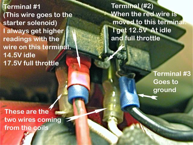
Nope. Not a type-o. The SH589 is listed in the table in your link right above the SH561. I was thinking that if the others were shunt style regulators, a diagram of an SH589 might help since google hits on sh561 were few. I get a lot of Kawasaki hits when searching. I found a manual for the HT3810 on line. http://www.hondapowerequipment.com/pdf/manuals/31750713.pdfIt looks like the far left is ground, the next 2 are the coil connections, the 4th is the IGN terminal and the far right is the Battery. It may be that the IGN terminal needs to be connected to the B+ connection when running. That's the only reason I can think of that the IGN wire goes to the Ignition switch. In the diagram it also shows it (IGN) connection to the B+ feed to the fuse block lending more credence to my theory that the IGN terminal needs B+ to function when running. Didn't know on the typo, thought Id ask. What could happen to the coils, rectifier etc.ĀĀ If the ground wire (far left)Ā and the Battery (far right) were hooked up wrong?ĀĀ In others words the Battery terminal got hooked to ground and the ground terminal got hook to battery.Ā The reason I ask is that when I look at the plug that plugs into the rectifier on the Honda tractor. ĀThe far left terminal wire is white -Ā the center terminal wire is blk with yellow stripe - and the far right terminal wire is black. That's different than what the wiring diagram seems to show.Ā I realize that there is really no way of knowing whether your seeing the plug from the front or back in the wiring diagram.Ā So I have just be assuming that I should go by what I see on the tractors plug. ĀFar left (1st) terminal Ā Center (2nd) terminal.Ā Far right (3rd) terminal is hooked to ground.ĀĀĀ (Battery is hooked in system). This morning when I check things again I got different readings than last night. The center 2nd terminal was putting out less than last night when I checked it. Reading off 1st terminal @ idle 14.5V........ ĀĀ @ full throttle 17.8V. Ā Ā Reading started at at 16.5V when I first made connection then built up to 17.8V Reading off 2nd terminal (center) @ idle 12.5V.........Ā @ full throttle 12.5VĀĀ Last night 13.5V idleĀĀ 13.5V full T Neither set of readings seem to be optimal.Ā The 14.5v is ok but the 17V is to high. The 12.5V would be ok but I'm not sure that the 12.5V is enough to keep the battery charged with the light on.Ā But maybe it would be.Ā The engine fires right up so I really don't need a whole lot from the battery. .
This message was modified Nov 2, 2011 by jrtrebor
|
jrtrebor
Location: Michigan - 3 hours north of Chicago on the lake
Joined: Feb 10, 2010
Points: 539
![]()
|
|
|
Re: Ariens Project #4
Reply #31 Nov 2, 2011 8:24 pm |
|
It doesn't make sense that the voltage in the one test was 13.5 at idle and only 12.8 at full throttle, unless the voltage regulator is sensing that the battery if full and is cutting back the charge rate.Ā maybe try the test again with the light on.ĀĀ If the charge rate with the light on and the battery connected, while not the idle voltage 12.8 should still maintain the battery.ĀĀ Good luck
Carl carlb. I revised some of the readings that I posted in my previous post.Ā I do get readings that seem to fluctuate not sure what that is about. I think it's time for me to end this thread or at least stop posting new information.Ā I need to keep reminding myself that the Rectifier that I am using is off a Honda garden tractor.Ā It has it's own electrical system. Lights,switches, relays, fuel pump, safety switches etc. That rectifier is not the correct one called for by Honda for my engine and coil combination.Ā So expecting to see voltage number that are what I think they should be is kind foolish on my part. It's not the correct rectifier. I'm getting at least 12+ volts at idle and full throttle out of the center terminal.Ā That should at least keep me from discharging the battery to a level below where it won't start the blower.Ā I would hope.Ā Running my light won't put much drain on the system. Maybe I will be able to find the correct rectifier at a price I can justify buying.Ā Normally they are around $120.00 to $140.00.Ā I only paid $130.00 for the engine. I've got a lawn mower junk yard about 20 miles from me. I will probably take a run by there and see what I can find.Ā Thanks for everyone's help, I've learned somethings.Ā Now I know enough to fill a shot glass, LOL.Ā I'm still open to any and all comments that you knowledgeable posters may have.
|
jrtrebor
Location: Michigan - 3 hours north of Chicago on the lake
Joined: Feb 10, 2010
Points: 539
![]()
|
|
|
Re: Ariens Project #4
Reply #34 Nov 6, 2011 12:17 am |
|
Check the battery voltage with the engine off, it should be around 12.5 12.6 volts.Ā If you can maintain 12.5 volts with the engine running and the light on you will probably be ok. I checked the battery, it was reading 12.5V.Ā At idle and full throttle with the light on I was getting a steady reading of 11.9V. I also disconnected both battery cables, and at both an idle and full throttle I got nothing out of the light.Ā Not even a faint dim glow. Even the two small LED marker lights I have showed nothing.Ā And those draw hardly any power at all.Ā That seems odd to me. Why would the coils not be putting out enough to at least light the LEDs??Ā I think I need to leave the battery disconnected and start over. See what readings I get right off the rectifier terminals. Or right off the coil wires themselves.Ā But that's AC I believe. And I'm not sure what readings to even look for, or to expect. It was easier to figure out and repower the blower than it's been to figure out this electrical stuff.,,, LOL sort of.Ā May I should just strap a car battery to it and throw a charger on it every once in a while.Ā This is making me crazy.
|
jrtrebor
Location: Michigan - 3 hours north of Chicago on the lake
Joined: Feb 10, 2010
Points: 539
![]()
|
|
|
Re: Ariens Project #4
Reply #36 Nov 6, 2011 8:47 am |
|
check the voltage coming out of the coil before the rectifier.Ā It should be AC but some of them are DC.Ā if you get an AC reading connect it to your rectifier and take a reading on the output side of the rectifier using the DC setting.ĀĀ If your coil is actually putting out DC you do not need the rectifier because the light doesn't care AC or DC and the Battery needs DC.
Good luck If it is AC coming out of the coil.Ā Any thoughts as to what kind of readings I may see on the meter?Ā Last time I tried reading the out put of the coils on the AC setting of the meter. I was seeing numbers that were no where near 12.xxV.Ā If I remember correctly they were in the 0.0xx range and they were constantly changing (maybe I had the meter hooked up wrong)?Ā Should I be seeing something around 12V.Ā Thanks!
This message was modified Nov 6, 2011 by jrtrebor
|
carlb
Joined: Nov 16, 2010
Points: 279
![]()
|
|
|
Re: Ariens Project #4
Reply #38 Nov 6, 2011 10:23 am |
|
Reading the voltage directly from the coils and not through the rectifier, Set the meter to AC and take a reading.Ā If the reading is strange switch the meter to DC and take the reading.Ā If you are getting a reading in the 12.5 to 15 Volt range your charging coils are putting out DC and not AC and you don't need the rectifier.Ā You may see higher voltages than that with no battery hooked up,Ā Even at 15vdc and only 10 total amps available you will not hurt the battery if the voltage is a little high. If you are getting DC voltage in that range you can hook up your coil directly up to the solenoid post and ground.Ā Make sure to connect the positive side of the output to the correct post on the solenoid, the ground can go to any ground point on the engine/frame. Remember take these readings without the rectifier hooked up.Good luck.
This message was modified Nov 6, 2011 by carlb
|
jrtrebor
Location: Michigan - 3 hours north of Chicago on the lake
Joined: Feb 10, 2010
Points: 539
![]()
|
|
|
Re: Ariens Project #4
Reply #39 Nov 6, 2011 4:30 pm |
|
Reading the voltage directly from the coils and not through the rectifier, Set the meter to AC and take a reading.Ā If the reading is strange switch the meter to DC and take the reading.Ā If you are getting a reading in the 12.5 to 15 Volt range your charging coils are putting out DC and not AC and you don't need the rectifier.Ā You may see higher voltages than that with no battery hooked up,Ā Even at 15vdc and only 10 total amps available you will not hurt the battery if the voltage is a little high.
If you are getting DC voltage in that range you can hook up your coil directly up to the solenoid post and ground.Ā Make sure to connect the positive side of the output to the correct post on the solenoid, the ground can go to any ground point on the engine/frame.
Remember take these readings without the rectifier hooked up.
Good luck. Well here is what I got. ĀAs I posted before there are actually four wires (two pairs) that come out from behind the shroud. Each pair are joined together to give you one wire with a connector on the end.Ā See photo in Reply #18.Ā (I never have really understood the two wires to one wire, unless there are four coils.Ā Maybe I should call Honda and see if they could give me an explanation). Black probe to grnd. Red probe inserted into the wire connector Engine @ idle reading from left wire - meter set to VACĀĀĀ 3.6V to 3.9V Engine @ idle reading from right wire - meter set to VACĀĀĀ 1.6V to 1.7V Engine @ full throttle reading from left wire - 12.5V steady Engine @ full throttle reading from right wire - 5.3V steady With meter set to VDCĀ Left wire 0.01VĀ Right wire 0.01V If I had to take an uneducated guess I would say that I may have a coil that's not right.Ā 5.3V compared to 12.5V. But what do I know. Maybe in all my switching wires around in the beginning trying to figure out the rectifier hook ups I burned up one of the coils.Ā I know there is a chance that I at one time I had the ground terminal on the rectifier swapped with one of the + output terminals on the rectifier. I had the first terminal and third terminal hooked up backwards. I think.Ā If I did would, or could that have burned out or damaged one or more of the coils?Ā If so, I guess that could explain the wide difference in readings between the two coil wires
This message was modified Nov 6, 2011 by jrtrebor
|
jrtrebor
Location: Michigan - 3 hours north of Chicago on the lake
Joined: Feb 10, 2010
Points: 539
![]()
|
|
|
Re: Ariens Project #4
Reply #41 Nov 6, 2011 9:49 pm |
|
Well from your readings it is putting out AC and not DC.Ā What reading do you get when you set the meter to AC and probe both wires at the same time.Ā If it is actually AC output you dont want to ground either of those wires.Ā You would only ground the negative wire after it was rectified to DC.
At this point I would take the shroud off and see exactly where the wires are coming from and how many coils you have.Ā Okay I pulled the flywheel.Ā I have two coils, each coil has two wires coming.Ā All four wires are the same color. One wire from coil "A" is joined to one wire from coil "B" The second wire from coil "A" is joined to the second wire from coil "B" The two wires that have connectors on the end that I have been connecting to the rectifier. Have a wire from coil "A" and coil "B" It is supposed to be a 10A coil system. Flywheel has 4 magnets. This mean anything to anyone? While I have things apart.Ā Is there a way for me to check the coils with an ohmmeter to see if they are okay? If so any thoughts as what kind of readings I should get if they are okay. And what I should see on the meter if they are bad, or partially bad or shorted. This morning I hooked an ohmmeter between the two coil wires. That is the two wires that have connectors on the end.Ā Not the two that come off of each coil. "I got a tone". I probably should have gone between a wire and ground as well.ĀĀ Maybe that reading would mean something to those that know about these things
This message was modified Nov 7, 2011 by jrtrebor
|
manjestic
Location: North Shore, MA
Joined: Oct 31, 2011
Points: 87
![]()
|
|
|
Re: Ariens Project #4
Reply #42 Nov 7, 2011 3:00 pm |
|
From your description of the splicing, the coils are in parallel.Ā A single phase rectifier fed by two coils to my mind implies the coils are in phase.Ā I'm not sure if each coil should have the same voltage output.Ā In parallel the voltage across them must be equal but independently, this is not true.Ā I'm thinking there is nothing wrong with your coils; there are two to produce more current than a single coil.Ā I'm a little rusty on this stuff.
Are you removing the splice?Ā How are you checking the coil voltages independently?
Since AC, wire color does not matter, your rect/reg will flip the negative half of the alternating current into positive.Ā Your voltage at the solenoid and battery will vary with RPM and battery voltage.Ā That is, even with a regulator, the output of the regulator will be higher when the battery is not at full capacity, than when it is at full capacity.Ā If your battery is significantly drained, I wouldn't necessarily be concerned about the high voltage on the output of your regulator (battery post).Ā I assume you are keeping a load on the output, as JimmyM says.
Paul
|
jrtrebor
Location: Michigan - 3 hours north of Chicago on the lake
Joined: Feb 10, 2010
Points: 539
![]()
|
|
|
Re: Ariens Project #4
Reply #43 Nov 7, 2011 4:06 pm |
|
Are you removing the splice?Ā How are you checking the coil voltages independently?
Paul Hi Paul I don't know or understand much about these type of things.Ā I had been checking the output by taking a reading from each wire with the meter set to VAC.Ā Red probe to to wire black probe to ground.Ā But I was assuming that each one of the two wires were connected to a single coil (that is the two wires that were being connected to the rectifier.Ā Which now seems not to be the case.Ā As you said, the coils appear to be hooked in parallel.Ā So I'll have to think about what that means as far as readings go. Thanks for your input. I know very little so any information is a help.Ā I tend to be able to understand what things do, but have no clue how some things work.
|
manjestic
Location: North Shore, MA
Joined: Oct 31, 2011
Points: 87
![]()
|
|
|
Re: Ariens Project #4
Reply #45 Nov 7, 2011 4:56 pm |
|
I had been checking the output by taking a reading from each wire with the meter set to VAC.Ā Red probe to to wire
black probe to ground.Ā But I was assuming that each one of the two wires were connected to a single coil (that is the two wires that were being connected to the rectifier.Ā Which now seems not to be the case.Ā As you said, the coils appear to be hooked in parallel.Ā So I'll have to think about what that means as far as readings go.
Am I correct in thinking that you were were alternately measuring each of the two wires across chassis ground.Ā I'd be interested in what the AC voltage across both wires (no chassis ground) is at idle and full throttle, and with and without the rectifier/regulator (and load) connected.Ā I hope I'm not covering ground already er...covered. What I'm after is how the two wires (representing the two coils in parallel) are connected to the rectifier.
|
jrtrebor
Location: Michigan - 3 hours north of Chicago on the lake
Joined: Feb 10, 2010
Points: 539
![]()
|
|
|
Re: Ariens Project #4
Reply #46 Nov 7, 2011 8:29 pm |
|
Am I correct in thinking that you were were alternately measuring each of the two wires across chassis ground.Ā I'd be interested in what the AC voltage across both wires (no chassis ground) is at idle and full throttle, and with and without the rectifier/regulator (and load) connected.Ā I hope I'm not covering ground already er...covered.
What I'm after is how the two wires (representing the two coils in parallel) are connected to the rectifier. Thanks carlbĀ - This is sometimes part of my problem I don't even know how to correctly hook up and check things.Ā And yes I was "measuring each of the two wires across ground".Ā I'll have to put things back together and take a measurement across both of the wires coming from the coils.Ā The readings given in the photo below were taken with the battery hooked in the system.Ā I hadn't checked it that day but when I checked it yesterday it was reading 12.4V.Ā I'll put it back in the charger and make sure it has a full charge. The diagrams that I have found for this rectifier. And the wiring diagram for the tractor that it came off of.Ā Show or call terminal #1 the Batt + terminal. The wire runs from the rectifier to the key switch B+ terminal.Ā Along it's way there it is tapped into and that wire goes thru a main fuse and connects to the Battery + terminal. Terminal # 2 is called or referred to as the Ign. terminal.Ā The wire goes from the rectifier to the key switch Ign. terminal.Ā Along its way there it is tapped into and that wire goes to a small 3 fuse, fuse block.Ā I hope some of this is making sense I really appreciate all you guys help with this.Ā I can do a lot of things. But I can get lost when it comes to this kind of stuff.Ā As you can imagine with me taking readings from the coils wires with one probe to ground.Ā I've simply been trying my best not to burn something up. By doing something stupid. That I didn't know was stupid to do.Ā You won't be insulting me by stating simple, (doesn't everyone know this) kind of things.
This message was modified Nov 7, 2011 by jrtrebor
|
carlb
Joined: Nov 16, 2010
Points: 279
![]()
|
|
|
Re: Ariens Project #4
Reply #47 Nov 8, 2011 9:08 am |
|
I must say i have not seen a rectifier with two hot output terminals on it, but it may be more common on tractors than snow blowers.Ā The light might be fine with the 17.5 volts while that would be too high for maintaining the battery.Ā Maybe use term 1 @ 17 volts for the light and term 2 @ 12.5 for batt charging.Ā Term one may be limited by a voltage regulator built into the rectifier
This message was modified Nov 8, 2011 by carlb
|
jrtrebor
Location: Michigan - 3 hours north of Chicago on the lake
Joined: Feb 10, 2010
Points: 539
![]()
|
|
|
Re: Ariens Project #4
Reply #48 Nov 8, 2011 10:09 am |
|
I must say i have not seen a rectifier with two hot output terminals on it, but it may be more common on tractors than snow blowers.Ā The light might be fine with the 17.5 volts while that would be too high for maintaining the battery.Ā
Maybe use term 1 @ 17 volts for the light and term 2 @ 12.5 for batt charging.Ā
Term one may be limited by a voltage regulator built into the rectifier I think there a few out there, but not many snow blowers have an on board 12v electrical system.Ā It's almost impossible to find information and any type of wiring diagrams for the setup I've got.Ā Actually I haven't found any.Ā That is why I've been using the Honda HT3810 tractors system as a guide for what I'm doing. I figure that it doesn't matter whether the system is on a tractor or a snowblower.Ā But maybe I'm wrong about that.Ā All I'm hoping to accomplish is to be able to run my light without draining the battery to the point the I can't use the electric starter to start it the next time out.Ā Last year with the 11hp Honda clone and the 3A coil. I never had a low battery problem unless I had been using the light for a while.Ā Usually if I did, I would throw a trickle charger on it overnight and things would be fine. The light is only got a 25 or 35W bulb so I'm not needing that much output from the coil(s) to keep the light running and at the same time be giving the battery a little charge. I'm going to put the flywheel back on this morning and take another reading from the coil wires.Ā Meter in VAC mode. With one probe to one wire and the other probe to the other wire. Then I'll make sure that the battery has a full charge. Hook it up in the system and take readings again off the starter solenoid terminal. Ā With the red wire on terminal #1 and then with it on terminal #2.Ā Would there be any reason, or would it make any sense to you.Ā That for some reason terminal #1 needs to be hooked directly to the battery. And terminal #2 should be hooked to the starter solenoid?Ā In other words that for some reason both output terminals of the reg/rec need to be hooked to something. Instead of the why I'm doing it which is to only have only one of the output terminals hooked to something?Ā I ask because the wiring diagram for the tractor shows the rec/reg hooked up that way.Ā In my last post I talked a little about how the tractor is wired from the rectifier.
|
jrtrebor
Location: Michigan - 3 hours north of Chicago on the lake
Joined: Feb 10, 2010
Points: 539
![]()
|
|
|
Re: Ariens Project #4
Reply #49 Nov 8, 2011 10:31 am |
|
Maybe use term 1 @ 17 volts for the light and term 2 @ 12.5 for batt charging.Ā
Term one may be limited by a voltage regulator built into the rectifier
Something just occurred to me after thinking about what you said.Ā The rec/reg I'm using is off that Honda tractor.Ā It has a few other components that are putting a draw on the system when it's running.Ā Like a fuel pump and a electric PTO clutch.Ā It also has all kinds of safety switches, buzzers, warning lights etc. So maybe that is why the output from terminal #1 is 17v.Ā The rec/reg was designed for that output to handle occasional heavy loads lights, etc. And the output from terminal #2 is a steady 12.5V for just normal load.Ā Not sure I put that into words to well.Ā As I've said before I have to keep reminding myself that this rec/reg was not designed to be used with my engine. The rec called for my engine is a Shindengen SH586B-12 an the one I'm using is a Shindengen SH561-12 Could be if I had the right one that the output from terminal one would be more in the 14-15V range. Just speculating.
|
carlb
Joined: Nov 16, 2010
Points: 279
![]()
|
|
|
Re: Ariens Project #4
Reply #51 Nov 8, 2011 4:46 pm |
|
it is very difficult to get a good reading on a charging system without some type of load or buffer such as a battery or light.Ā You may be seeing very high voltage with no load but it will normally drop substancially when a load is applied. I would hook up the light to term 1Ā and the battery to the term 2Ā Then take a reading off both terminals both with the light on and the light off. Voltage reading at an idle really isn't necessary as it will usually be low. This is how i would hook it up.Ā The worst that can happen is you burn out the bulb which i doubt or you undercharge the battery which wont really hurt anything. If this is the best that you can achive with this regulator that is what i would do.Ā You may have to put the battery on a trickle charge after use if the battery gets too low.Ā If you don't have to use the light you should not have any problems. Good Luck
This message was modified Nov 8, 2011 by carlb
|
jrtrebor
Location: Michigan - 3 hours north of Chicago on the lake
Joined: Feb 10, 2010
Points: 539
![]()
|
|
|
Re: Ariens Project #4
Reply #53 Nov 9, 2011 8:24 pm |
|
I would hook up the light to term 1Ā and the battery to the term 2Ā
Then take a reading off both terminals both with the light on and the light off.
Voltage reading at an idle really isn't necessary as it will usually be low.
This is how i would hook it up.Ā The worst that can happen is you burn out the bulb which i doubt or you undercharge the battery which wont really hurt anything.
If this is the best that you can achive with this regulator that is what i would do.Ā
Good Luck Well, I hooked up term 1 to the starter solenoid.Ā And term 2 directly to the battery + post.Ā Took reading off the battery + post @ idle 14.6V @ idle with the light on 13.3V @ full throttle 14.6v @ full throttle with the light on 14.3V That would be a good reading. I guess for some reason I needed to have both terminals hooked up.Ā Don't have any idea why that would be.Ā But I believe that 14.5V @ FT is an acceptable reading. Yes? Checked today the light is 35W
This message was modified Nov 9, 2011 by jrtrebor
|
|
|